|
|
Post by Rapetou33 on Aug 19, 2013 7:04:51 GMT -5
Hello, I am trying to build a lightpen with the explanations found on "playvectrex" but need to know which wires I have to connect. I have bought several cables but the colours are never the same and I don't know what pin is GND, SW7 and +5V. Thanks for your help  |
|
|
|
Post by hcmffm on Aug 19, 2013 17:52:16 GMT -5
Hello, I am trying to build a lightpen... Hey, Olivier, only original hardware is allowed during the Vector War! ;-) |
|
|
|
Post by Rapetou33 on Aug 20, 2013 2:33:23 GMT -5
" DARN IT ! " I confess I would have written my scores directly on the screen rather than wasting time, nerves, and neurones on playing ...  To move back to my question : ask if necessary because I am avare it may not be clear I am not really skilled at electronics (either) |
|
|
|
Post by marblemad on Aug 20, 2013 6:46:48 GMT -5
Hello, I am trying to build a lightpen... Hey, Olivier, only original hardware is allowed during the Vector War! ;-) get yourself a meter. a cheap one will do. use continuity mode to identify which pin corresponds to what coloured wire and then use the DC mode to double check you have your 5v and GNDin the right place. |
|
|
|
Post by Rapetou33 on Aug 20, 2013 15:54:47 GMT -5
I'll do that, thank you
|
|
|
|
Post by gauze on Aug 8, 2018 9:24:34 GMT -5
for the record it's pins 4 (fire button 4/SW7), Pin 7 (+5VDC) and Pin 8 (GND)
pins are numbered when looking into the port from front of console:
1 2 3 4 5
6 7 8 9
pins are numbered when looking at controller plug end on:
5 4 3 2 1
9 8 7 6
the sega genesis extension cables I got in 2018 are wire colors: white (+5vdc), blue (gnd) and orange (pin 4/sw7)
|
|
|
|
Post by gauze on Aug 15, 2018 14:41:26 GMT -5
|
|
|
|
Post by Malban on Aug 15, 2018 15:57:53 GMT -5
Looks pretty similar to me...
|
|
|
|
Post by gauze on Aug 15, 2018 16:34:05 GMT -5
yeah look at the PCB layout too (MVLP tab) I had to manually add some lines and stuff that's what I am concerned with.
The schematic I just copied it so I think that's fine.
|
|
|
|
Post by Malban on Aug 15, 2018 17:14:04 GMT -5
Still sort of looks ok. two things though, the schematics and the MVLP do not fit: a) in the MVLP R3 is also a 10k resistor (instead of 1k), but looking at the original the 10k seems to be "correcter" it seems one displays the "Prefix" and the other the "Name" - perhaps check that out in your BOM b) the transistor is "labeled" Q2 instead of Q1 - but labels don't really matter.
Just todayI ordered some inverters, if you want to replace your NAND and are into SMD soldering and want to save some space I guess you can also use: SN74LVC1G14DBVR
Regards
Malban
PS
Today I had success with my "though hole" circuit (also using NAND)
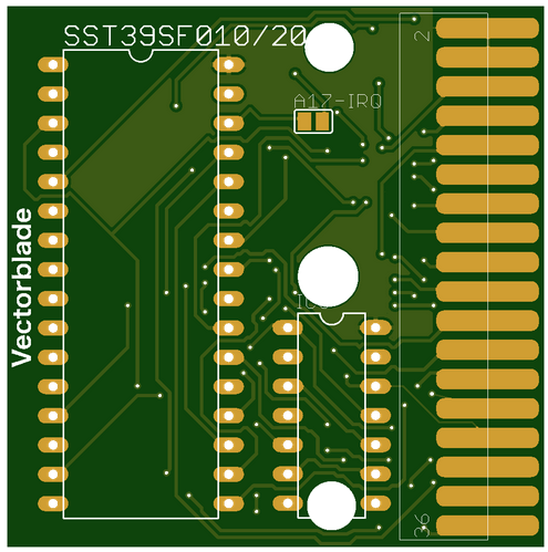
Now I changed the design to completly SMD parts, that can "easily" be ordered with the PCB. Ordered a new PCB and will test it out soon... If that is working it will be the final Vectorblade design: 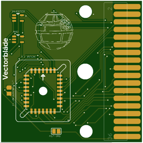
|
|
|
|
Post by gauze on Aug 15, 2018 18:49:42 GMT -5
both resistors are labeled 10k on the pcb layout, the schematic label I did was wrong. I'll look at changing the BOM. I can't see well already SMD soldering is out of the question |
|