|
|
Post by vectrexrc on Mar 26, 2015 17:33:37 GMT -5
Does anyone know how to draw a patterned line? eg. dotted or dashed etc
I think the standard bios line drawing routine is solid line only.
I think there is bios routine to draw a vector object with a pattern, but but how to just draw a single line that is patterned?
Is it possible?
Is it inefficient in terms of cycles to draw with patterned lines?
Any advice would be great.
|
|
|
|
Post by jfmateos on Mar 27, 2015 0:50:54 GMT -5
I think you only have to store the patter in $C829 before calling Draw_Line_d
Drawing a patterned line is as efficient/fast as drawing a solid line... in fact, the solid lines are also patterned lines with pattern $FF
|
|
|
|
Post by binarystar on Mar 27, 2015 5:33:18 GMT -5
Yeah as JFMateos says, change the pattern in $c829. $FF is default - a solid line. IIRC, each bit in the byte represents one line segment and one/(two?) of the bits determines whether the line has a dot at the beginning/end.
|
|
|
|
Post by cNp on Mar 27, 2015 7:47:16 GMT -5
Good to know, thanks... been meaning to ask after this as I tried using different drawing routines (never really understanding the differences) to see any difference and found one that drew a dashed line on the emu... but it drew a solid line on real hardware so I just gave up on it.
Another thing I have to look at is pulling the draw bios routine I use out as an inline macro... when I looked before it didn't seem as simple as pulling other routines out...
cNp
|
|
|
|
Post by gauze on Oct 18, 2016 13:15:42 GMT -5
anyone have any clue on what these expected "patterns" are? I messed around with a few things using Draw_VLp ($F410) but I haven't figured out what exactly happens except for values >=128 (high bit set on, continue processing data behind pointer in X-reg), even after reading the code (does some VIA register fiddling which controls D/A gun control type stuff?).
Note I have only checked in VIDE and ParaJVE not a real vectrex.
I did find this in BIOS but I couldn't reproduce any dashed/dotted lines in my emulator tests using Draw_VLp, just get either
a visible line or an invisible line, no dashing.
; Line patterns for boundary boxes
DF0FD: FCB %11100000
FCB %00111000
FCB %00001110
FCB %00000011
|
|
|
|
Post by Malban on Oct 18, 2016 14:11:45 GMT -5
Hi, doesn't suprise me - the BIOS Draw_VLp is buggy. It doesn't work as expected. If you use Vide use a patterned line in vecci and build a runnable from it. For the "export" I did an own Draw_VLp which works as expected. In general a pattern is a "bit"-pattern, for each 1 a "dash" is drawn for each "0" a blank is drawn. If you have eight dashs in a row that is a solid line - everythings else something in between. Patterns must have the highest bit set, since 0 there is the "end" criterium for the list. If you want to use BIOS routines, than use: F434 Draw_Pat_VL_a ; F437 Draw_Pat_VL ; F439 Draw_Pat_VL_d and set the pattern to $C823. Also worth noting - the dashes get "longer" with vector strength, the "count" of dashes changes with scaling. Regards Malban (The patterns in vecci are not drawn 100% correct! - That will not change :-)) 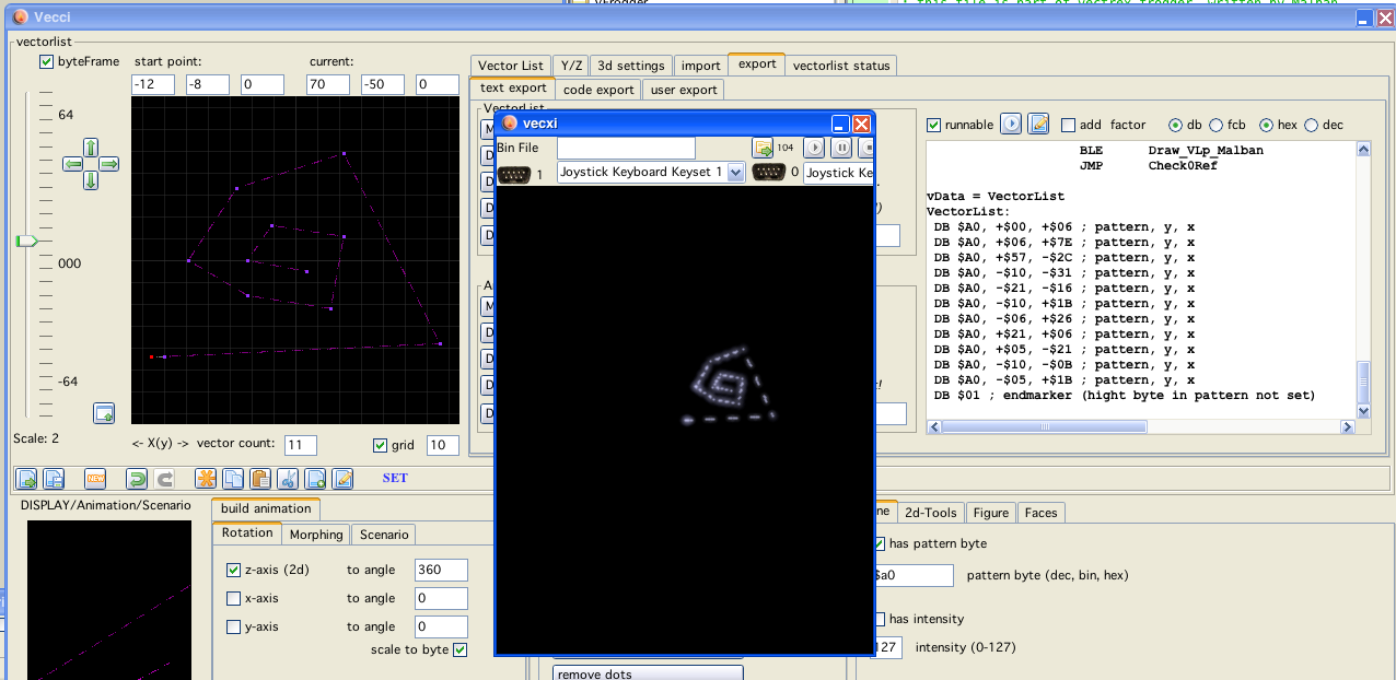 |
|
|
|
Post by gauze on Oct 19, 2016 11:39:10 GMT -5
Hi, doesn't suprise me - the BIOS Draw_VLp is buggy. It doesn't work as expected. blam |
|
|
|
Post by limitzer0 on Oct 2, 2019 0:45:30 GMT -5
I just spent way too long messing with Draw_VLp… I wish I found this sooner.
|
|
|
|
Post by gtoal on Oct 20, 2019 11:24:45 GMT -5
I just spent way too long messing with Draw_VLp… I wish I found this sooner. you might also look for drawSyncList - something I wish I'd found sooner. G |
|
|
|
Post by D-Type on Apr 25, 2020 16:37:22 GMT -5
I just spent way too long messing with Draw_VLp… I wish I found this sooner.
Anyone have any simple code samples for patterned lines they can share with me on this, please?
I can't seem to get anything other than solid or blank lines.
UPDATE: OK, I literally got something working on my next compile. Would still like some samples though, please! :-)
Here's my code (in Forth):
here equ planeA
 00 c,  6E c,   \ rel y, rel x
 14 c, -1E c,
 00 c, -32 c,
 14 c, -1E c,
-28 c,  00 c,

: md_reset/move \ y -- ;
   _Reset0Ref 0 swap _Moveto_d
;

\ ;$FF ENABLES DOTTED LINE
\ ;$00 REQUESTS BLANK LINE
\ ;$02 IS SOLID LINE
\ ;$01 DELIMIT

: draw \ -- ; Draw tests.
   begin
      _Wait_Recal
      _Intensity_7F

       $3F VIA_t1_cnt_lo c! \ Set scaling factor
       $AA Vec_Pattern c!

      -$30 md_reset/move  4 Vec_Misc_Count c!  planeA _Draw_VL     \ Works OK
      -$50 md_reset/move  4 Vec_Misc_Count c!  planeA _Draw_Pat_VL \ Needs work...

      key?  \ press a key to end
   until
   key drop
;
|
|
|
|
Post by D-Type on Apr 25, 2020 17:31:10 GMT -5
OK, I've sussed this - I guess I can do without code samples now! First thing I did was comment out the code that sets a static pattern, from the compiled code i.e. \ $AA Vec_Pattern c! Then, from my Forth command prompt, if I set the pattern in $c829 and then run the Draw word (i.e. sub-routine) I get dashes. Setting to %10000000 gets me dots, then %1100... gets me short dashes, all the way to %11111110 to get very long dashes with a dot-sized gap. What is weird is that there is a constant number of dashes per vector, so on the display, from the PlaneA vector list I'm using, there is a vector that is about 3cm long and it has 4 dashes in it, the next vector is 1cm long and also has 4 (smaller) dashes in it. Same 4 vectors in all the others in the VL, regardless of their length. So if you reset your Vectrex and look at the startup banner with two rectangles of moving clockwise/anti-clockwise dashes, these show the same thing i.e. same number of dashes for horizontal sides and vertical sides, regardless of length. Mind blown  OK-0 %10000000 $c829 c! draw
OK-0 %11000000 $c829 c! draw
OK-0 %11100000 $c829 c! draw
OK-0 %11110000 $c829 c! draw
OK-0 %11111000 $c829 c! draw
OK-0 %11111100 $c829 c! draw
OK-0 %11111110 $c829 c! draw
|
|