|
|
Post by kokovec on Dec 16, 2023 15:41:26 GMT -5
Just something I've been experimenting with.
I started out just wanting to be able to use a decent but cheap USB gamepad with the Vectrex and then got a little carried away.
|
|
|
|
Post by gtoal on Jan 10, 2024 15:30:54 GMT -5
By coincidence (I wasn't aware of your experiment when I started it) I'm working on a USB to Vectrex universal converter as well. And by another coincidence, another developer I know is making one too (not mentioning who at this point as I don't know if he's made it public yet) - mine uses a Pi Zero running Linux to handle the USB controllers and I think my friend's one is some variety of MCU (such as an ESP32 or ESP8266 or whatever). So 2024 should be a good year for people with USB joysticks. (I'm hoping to also allow a USB mouse with mine). Finally got the parts I needed yesterday so am breadboarding mine right now. Maybe will have something to demo by the end of this weekend.
|
|
|
|
Post by kokovec on Jan 11, 2024 11:19:54 GMT -5
One good idea always breeds another. I was actually working on another project, for another system, and decided to reuse the pieces to make the Vectrex USB thing. I got tired of having the breadboard on my desk, so I decided to build a dev board. To be honest, I'm not sure if I'll make these available to purchase as I don't really have much time to devote to it. Also, it would be too expensive to produce in small quantities. In any case using a Pi Zero with Linux makes the most sense. It abstracts out the need to deal with all the lower-level stuff like enumeration and setting up transfers. For those who are interested: My implementation uses a PSOC-5 that's tied to a Vinculum VNC2 USB host controller. The analog joysticks are driven by Analog Devices 8-bit digital pots. The Pot that has a knob on it, on the edge of the board, handles mouse sensitivity (velocity control). The blue trim pots are used to center the joysticks. So far it will only handle an Xinput controller (like the venerable Logitech G F310).  |
|
|
|
Post by gtoal on Jan 17, 2024 23:35:52 GMT -5
Initially the buttons were easy as they just connected directly to the Pi's GPIOs. How did you handle the digipots needing a positive VL when we want to feed them with VL=-5V and VH=+5V for the joystick control? My first attempt failed as the MCP42010 digipots did not take well to being fed -5V and +5V. Same problem when I tried DS3502 digipots. (by the way, the DS3502 are I2C chips and the MCP42010 is SPI - lots of time wasted there working out how to drive each of those from C. All the demo code on the net is in python :-( ) My next attempt was to redefine GND as the -5V supply from the Vectrex so that the digipot thinks it is dealing with VL=0V and VH=10V but this meant that the Pi Zero was running on GND=-5V and VCC=0V rather than GND=0V and VCC=5V. This was now good for the joystick values but messed up control of the buttons which could no longer just be connected directly to the GPIOs. I tried to work around that by using SSRs to press the buttons (crazy, I know) but that messed up completely because I didn't realise that, unlike mechanical relays, SSRs could only switch AC loads :-( Incidentally, I wanted to power the pi from the Vectrex cable but it's not safe to feed that unregulated 5V directly into a Pi, and the USB voltage converter I was using barfed when connected to 0 and 5V from the vectrex, so the hack above gave me a chance to feed -5V and +5V into the USB voltage converter and that actually did make a good supply. But now I'm back to using the normal 0V - 5V supply for the Pi and an op-amp to convert the VL=0V and VH=5V from the digipots into the positive and negative voltages that the vectrex joystick inputs require, but I haven't used op-amps before and am slightly unsure of the details. This is what I'm looking at so far. Do you have a better way? (Also, do the joystick X and Y inputs expect -5V to 5V or -2.5V to 2.5V - I've read differing statements about that. If it does need -2.5 to 2.5 then I think a simple voltage divider with 2 resistors should work on the output from the op amp?) (and because of the lack of a 5V regulated supply, I've had to power the Pi from a separate power supply which I really didn't want to do, to minimise cabling) 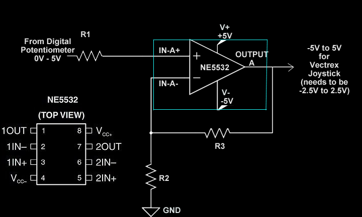 By the way, the overall circuit is pretty much just the standard controller one, with the joystick pots replaced by digipots, but buttons 1 through 4 coming directly from Pi GPIO pins. 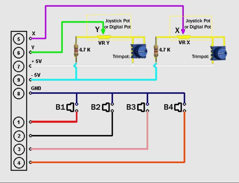 |
|
|
|
Post by gtoal on Jan 22, 2024 0:06:21 GMT -5
A quick status update. I stripped down my breadboard that was using the Vectrex joystick circuit and rebuilt it again more neatly from first principles: 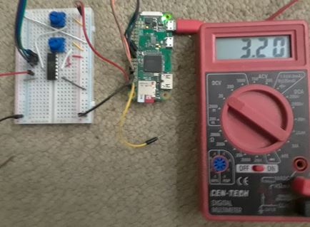 This circuit (controlled by the Pi) outputs 0 - 3.2V with 256 steps for X and for Y, after adjusting the trimpots to bring it down from 0 - 5V. (I found an older post that said the joystick range was from -3.2V to +3.2V, and a check with a meter showed that to be in the ballpark). Tomorrow's job is to feed that into an op-amp circuit fed by +5V to -5V to both shift it down and scale it up by a factor of 2 so that 0 - 3.2V maps to -3.2V - +3.2V. After a day of reading up on op-amps I think there's a chance I'll manage it (although getting this far has cost me one fried op-amp and one completely dead pi-zero-w :-( ) but if someone were kind enough to spell out the circuit to do that transformation (with +5V, 0V and -5V rails available) I would jump right on it! Analog electronics is not my strong suit. |
|
|
|
Post by gtoal on Jan 24, 2024 3:26:44 GMT -5
Got it working :-) 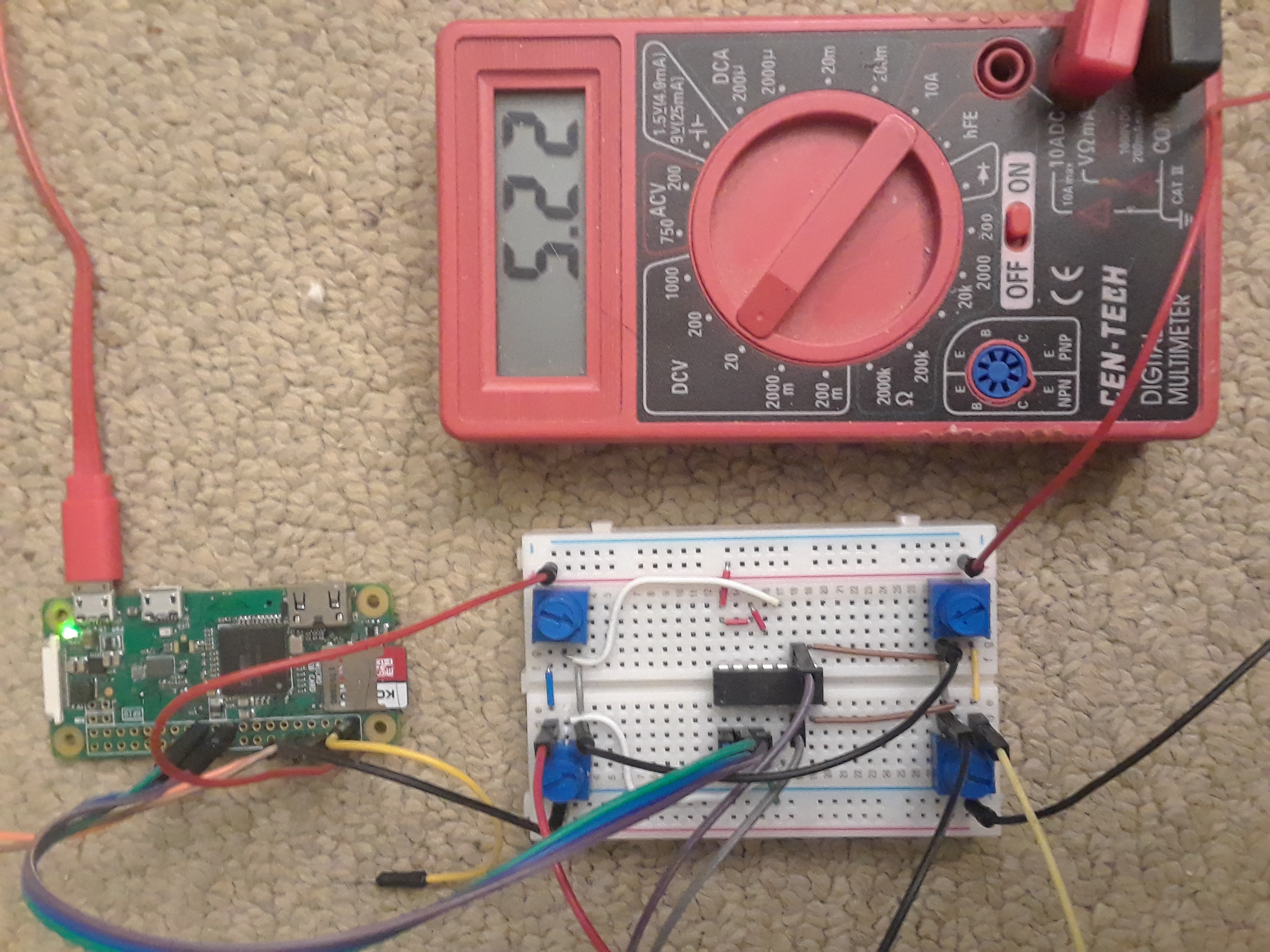 At the end of the day all that was needed was an MCP42010 and four trimpots. Each trimpot is used as a voltage divider - one for the +5v to gnd and one for gnd to -5v; one pair for X and one pair for Y. I did have to power the Pi externally though, it got into a reboot loop when I tried to power it directly from the Vectrex's 5V. Since the Pi has external power, any Pi will do - it doesn't have to be a Zero. Assuming you have a Pi already, the most expensive component to build one of these is likely to be the cable :-) |
|
|
|
Post by gtoal on Jan 24, 2024 11:31:00 GMT -5
Here's the circuit diagram: 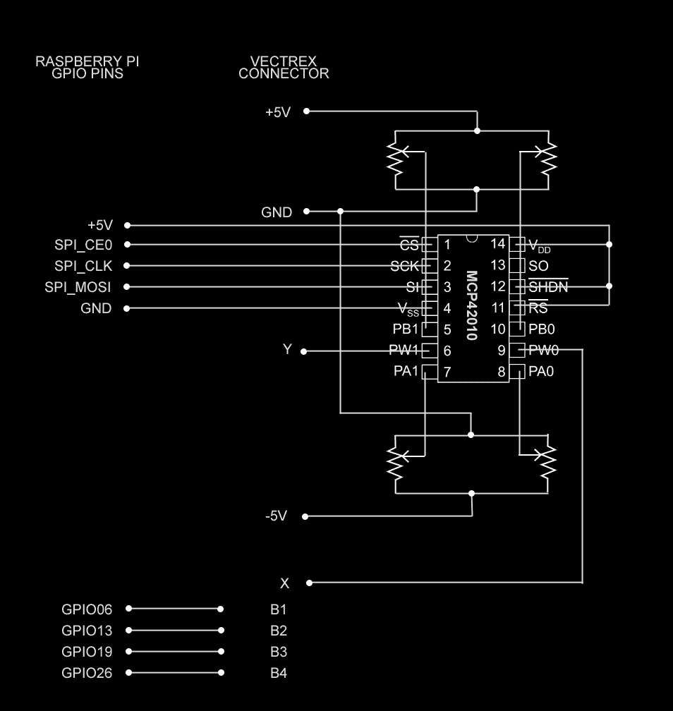 Later note... we solved the problem mentioned below by adding opto-isolators to the four buttons. The final circuit is pretty much identical to the diagram above apart from the addition of those 4 (very cheap!) opto-isolators. |
|
|
|
Post by gtoal on Jan 24, 2024 13:42:29 GMT -5
I tested the buttons separately from testing the joystick. Each worked great when tested on their own. But when I put the two together, hooking up the button wires from the Vectrex to the GPIOs (which have to be in HIGH state for an unpressed button) caused significant distortion on the joystick positioning. I've put a transistor on the buttons so that the Pi's 3.3V isn't directly shorting to the Vectrex's ground! It now works...  |
|
|
|
Post by kokovec on Jan 25, 2024 12:06:20 GMT -5
I tend to look for the simplest solution. In this case I used a digi pot capable of handling +- voltages. I had a couple of Analog 5290 8-bit digi pots in my parts box so that's what I used. Ideally a 16-bit +-V tolerant digi-pot would have been better, but resolution issues are mitigated by the +-3.5V range needed by the Vectrex (when using a +-5V reference into the digi-pot). Here's the schematic of what I built.  |
|
|
|
Post by kokovec on Jan 25, 2024 13:15:02 GMT -5
BTW...
When I was measuring the voltage range while adjusting the centering pots, I found that the sweet spot seemed to be around +-3.2V.
This, of course is a factor of the linear impedance specs of the digi-pots and tolerances of the physical pots and resistors.
|
|
|
|
Post by gtoal on Jan 28, 2024 2:43:38 GMT -5
I forgot to mention - using the transistor to press the button caused the Joystick value to jump when the button was pressed. I solved that problem by using opto-isolators to press the buttons rather than transistors. The final circuit is pretty simple and should be cheap to build. I've started a writeup on how to build one at gtoal.com/vectrex/joystick/USB-to-Vectrex.html - lots of detail still to be added but the overall picture is in place. I spent an hour playing Tailgunner using my Sidewinder USB joystick, so it definitely works :-) This version is only for one joystick port, but fortunately SPI supports two devices so adding the second port would just be a case of duplicating the digipot and the 4 opto-isolators. The Pi has more than enough GPIOs to do it all. |
|
|
|
Post by gtoal on Feb 19, 2024 21:18:13 GMT -5
|
|
|
|
Post by kokovec on Feb 21, 2024 17:09:26 GMT -5
No apologies necessary. This is a great community of enthusiasts and builders. There's room for everyone to showcase their ideas. |
|